
Flex Circuit Tested for Quality
As its name implies, a flex circuit is a printed circuit board with flexible components and traces. They are usually fabricated using polyamide or polyester films. Unlike rigid PCBs, flex circuits are designed to withstand a wide range of environmental conditions. They also allow for high component density and a more compact form factor.
Despite the flexibility of a flex circuit, it is still crucial to test these boards for quality prior to production. In addition to electrical testing, a flex circuit must undergo structural tests as well to ensure that it can withstand the demands of its end-use environment. Traditionally, these tests have been performed after the assembly and testing process, but advanced rigid-flex boards are now being used to perform these tests during production.
The first step in determining the quality of a flex circuit is visual inspection. This involves a trained operator thoroughly inspecting the boards for welding defects, scratches, delamination, and other visible issues. Visual inspections are a critical part of the manufacturing process and can help identify issues that would be difficult to detect by other methods.
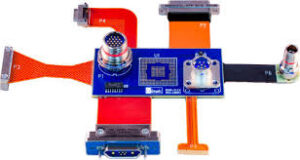
How is a Flex Circuit Tested for Quality?
Once the visual inspection has been completed, the flex circuit must undergo dimensional testing to verify that it meets specified tolerance limits. This typically involves the use of precise measurement tools to assess the thickness, width, and length of each flex circuit. The measurements must be within predefined tolerances to prevent potential issues with the final product.
Another important element of flex circuit testing is the bend test. This test enables manufacturers to determine the maximum amount of bends that can be endured by the circuit without damaging the copper. The flex circuit should be able to tolerate at least one full cycle of bending and folding. A proper design can minimize the number of bends needed to maintain circuit integrity. For example, the design should avoid 90o bends that cause high strain and use gradual and large curved angles to prevent circuit damage. Plated through-holes and component placement should also be avoided near the bend areas. In multi-layered flex circuits, conductors traversing a bend area should be perpendicular to the bending axis and staggered to improve efficiency.
Flex circuits should also undergo X-ray testing, which can detect hidden soldering defects that might not be visible by other testing techniques. These defects include bridging, voids, and insufficient solder under components or between layers of the rigid-flex PCB. In-Circuit Testing (ICT) can also be used to check for these defects in a flex circuit, which is an extremely powerful method of ensuring that the rigid-flex PCB can function as intended.
The best way to ensure a high-quality flex circuit is to start with a good design and adhere to IPC standards. These standards are available online and are constantly being updated and fine-tuned. However, Solberg emphasized that these documents should not be used as a “silver bullet” for a successful flex PCB design, but rather to provide a foundation of knowledge that the designer can build upon with their experience and resources.